Feature:
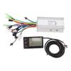
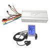
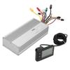
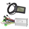
1. Electric Bicycle Motor Controller: Can provide stable speed and sensitive control of braking and direction changes.
2. Controller S866 LCD Display Kit: Using ABS material, light, rainproof, durable, LCD backlight display, can clearly display status and data.
3. Good Heat Dissipation Function: Controller shell is made of metal with groove design, which can protect the internal circuit and avoid thermal overload.
4. Control Setting Functions: Power switch control, wheel Diameter setting, idle speed automatic sleep time setting, backlight brightness setting, startup mode setting, drive mode setting, voltage level setting, controller limit value setting.
5. Strong Compatibility: LCD instrument controller kit is used to convert the lithium battery of bicycles or scooters into electric riding, usually suitable for 1000W motors.
Specification:
Item Type: S866 LCD Instrument and Controller Kit
Color: As Pictures Shown
Booster: 1:5
Material: Aluminum Alloy + ABS Plastic
Weight: Approx.714g 25.2oz
Controller Rated Voltage: DC 36V 48V
Controller Maximum Current: 30A
Controller Speed Setting: 1 4.2V
Controller Brake Input: Low Level
Applicable Motor Power: 1000W
Controller Box Size: Approx. 149x84x42mm 5.9x3.3x1.7in, Meter Size: Approx. 81x48mm 3.2x1.9in
Controller Wire Color Definition:
1. Yellow, Green, Blue Single Big Head Wire: Motor Wire
2. Red white black blue green yellow Double Row Six wire Port: Motor Wire
3. Red and Black Single Big Head Line: Power Line
4. Red, Blue, Black, Green and Yellow Single row Five wire Port: Instrument Line
5. Black and Yellow Lines (two): Power off Brake Handle Line
6. Red and Black Lines: Throttle Dial Line
7. Brown black yellow Line: Power Sensor Line
8. Black and Red Lines (two): Headlight Lines
Meter Working Voltage: DC 24v, 36v, 48v, 60v Compatible (meter Selection Setting).
Instrument Function Description:
1. Display Function: Speed Display, Battery Indicator, Fault Indicator, Total Mileage, Single Mileage
2. Control Setting Functions: Power Switch Control, Wheel Diameter Setting, Idle Speed Automatic Sleep Time Setting, Backlight Brightness Setting, Startup Mode Setting, Drive Mode Setting, Voltage Level Setting, Controller Limit Value Setting.
3. Communication Protocol: Uart Displays All the Contents of the Screen (full Display After Power on for 1s)
3.1 Display of Battery Power and Remaining Power of Bms.
3.2 Multifunction Display Area: Total Mileage Odo, Single Mileage Trip (unit: Mile, Km), Single Boot Time Time, Battery Voltage Vol, Dst: Battery Life
3.3 Speed display Area
Avg: Average Speed, Max: Maximum Speed, Speed: Current Speed: Unit Mp h Km h
The Speed Signal is Taken from the Hall Signal in the Motor and Sent to the Meter by the Controller. (the Time of a Single Hall Cycle, Unit: 1ms) the Instrument Will Calculate the Real Speed According to the Wheel Diameter and Signal Data (the Number of Magnets Required by the Motor Hall)
3.4 Vehicle Power Gear Adjustment, 0 9 Digital Display and Gear Bar Display;
Instrument Environment Setting Instructions:
P01: Backlight Brightness Level 1 is the Darkest and Level 3 is the Brightest;
P02: Mileage Unit, 0: Km: 1: Mile;
P03: Voltage Level: 24v 36v 48v 60v 64v (default 36v)
P04: Sleep Time: 0, No Sleep. Other Numbers Are Sleep Time, Range: 1 60 (in Minutes).
P05: Help Gear: 0, 3 Gear Mode, 1, 5 Gear Mode.
P06: Wheel Diameter: Unit. Inches; Accuracy: 0.1; This Parameter is Related to the Display Speed of the Instrument, and Needs to Be Entered Correctly.
P07: Speedometer Magnet No.: Range: 1 100.
This Parameter is Related to the Speed Displayed by the Instrument and Needs to Be Input Correctly; if It is an Ordinary Hub Motor, Directly Input the Magnetic Steel; if It is a High speed Motor, It is Also Necessary to Calculate the Reduction Ratio, Input Data = Number of Magnetic Steel x Reduction Ratio.
For Example: the Number of Motor Magnets is 20, the Reduction Ratio is 4.3: the Input Data Is: 86 = 20 x 4.3
P08: Speed limit: Range 0 100km h, 100 Means Unlimited Speed.
The Data Entered Here Represents the Maximum Running Speed of the Vehicle: for Example, Input 25, Which Means That the Maximum Running Speed of the Vehicle Will Not Exceed 25km h; the Running Speed Remains the Set Value, the Error: 1km h; (power and Steering Speed Limit).
Note: the Values there Are in Kilometers. when the Unit Setting is Converted from Kilometers to Miles, the Speed Value on the Display Interface is Automatically Converted to the Correct Mile Value, but the Speed Limit Value Set in This Menu Under the Mile Interface is Not Converted. the Mile Speed Does Not Match the Actual Speed Limit.
Note: P09 P15 Menu is Only Valid in Communication State.
P09: Zero Start Non zero Start Setting, 0: Zero Start. 1. a Non zero Start.
P10: The Drive Mode is Set to 0: Power Drive (how Much Power is Output is Determined by the Power Gear, the Switch is Invalid).
1: Electric Drive (driven by Turning the Handle, when the Power Gear is Invalid).
2. Electric Drive and Electric Drive Coexist.
P11: Help Sensitivity Setting Range: 1 24.
P12: Help Start Strength Setting Range: 0 5.
P13: Power Magnetic Steel Disk Type Setting 5, 8, 12 Magnetic Steel Type.
P14: Controller Limit Value Setting Default 12a, Range: 1 20a.
P15: Controller Under voltage.
P16: Odo Reset Length Press 5 Seconds to Reset Odo to Zero.
P17: 0: Disable Cruise, 1: Enable Cruise. Auto Cruise Optional (only Valid for Protocol 2).
P18: Display Speed Ratio Adjustment, Range: 50percent 150percent .
P19: 0 Power Bit, 0: 0, 1: Excluding 0.
P20: 0: 2 Protocol 1: 5 S Protocol 2: Standby 3: Standby..
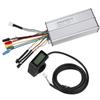
Package List:
1 x Controller1 x Controller Wiring Instructions1 x Meter1 x Instrument Manual
Note:
Use the product that complies with the communication protocol.