Description
:
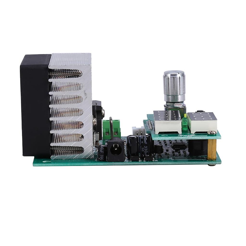
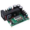
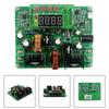
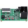
New design, simple and versatile electronic load! Automatic memory function with all parameters , is well suited for
automated assembly of the power adapter aging(burn in) module.
Features
:
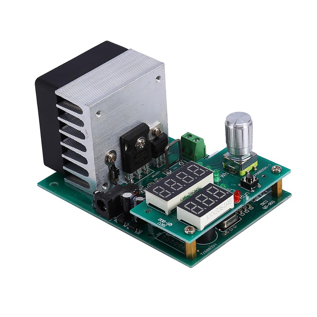
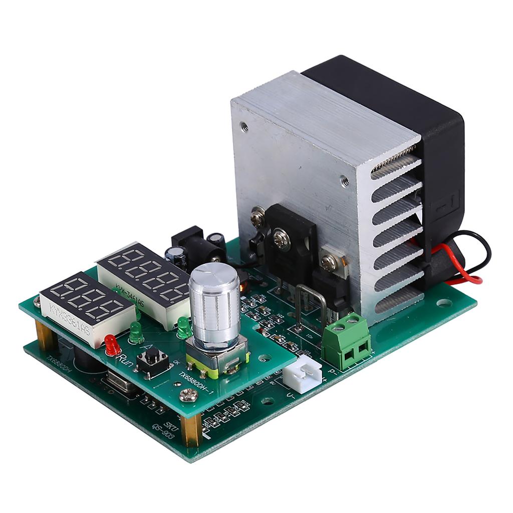
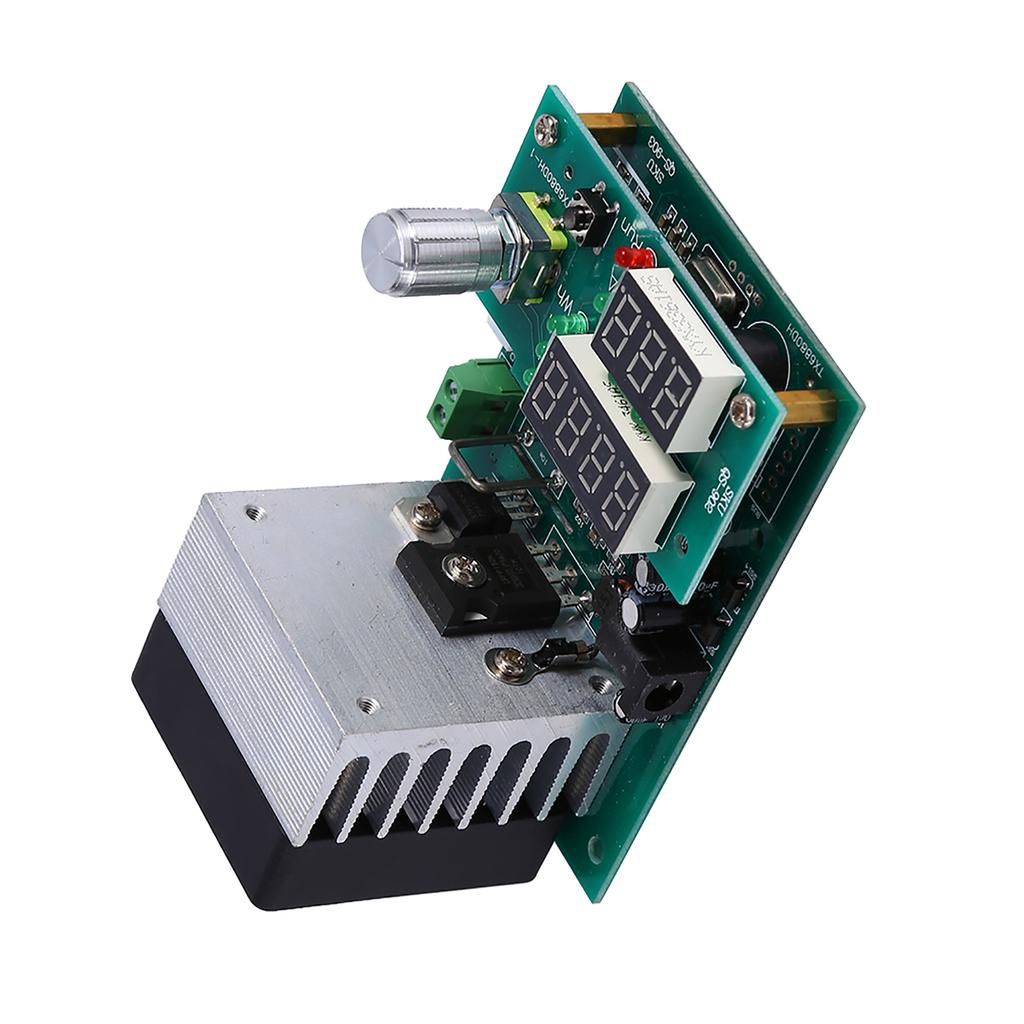
1, Simple and versatile electronic load.
2, Automatic memory function with all parameters , is well suited for
automated assembly of the power adapter burn in module.
3, In the sale
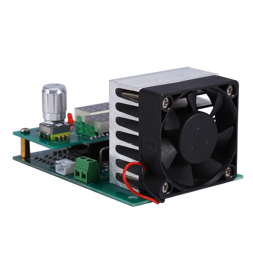
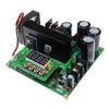
of the latest version, slightly larger size and upgrade the fan into
the original 5020 Delta high speed dual bearing fan.
4, Higher cooling
redundancy, more suitable for long hours.
5,
Multi functional
, can also be used to test battery.
Specifications
:
Power Supply Requirement: DC 12V voltage ( actual voltage 11 14V) current is
not less than 0.5A of power, the power will be displayed inappropriate
Err6.
Operating Modes: Single mode constant current (CC).
Discharge current: 0.20 9.99A stepper 0.1A or 0.01A
Discharge Current Maximum Error: 0.7percent 0.01A
The Maximum Capacity Test Error: 0.5A 2.5percent , 2A 1.5percent , 5A and above 1.2percent
Offline ( termination ) Voltage Range: 1.0 25.0V stepping 1V or 0.1V
Discharge Voltage: 1.00 30.00V
The Maximum Voltage Measurement Error: 1percent + 0.02V
Maximum Power: 60W super power automatically limits the maximum current (for
example, up to 60W when it can open 9.99A 6V and 20V maximum at the only
open 3.00A)
Highest Battery Test Statistic: 999.9Ah or 9999Wh, achieve value stop testing ( first value to those who stop condition )
Board Size: 60W 100mm x 70mm x 57mm ( fan prominent board about 12mm)
Positioning Hole Locations: 60mm x 88mm Diameter 3.2mm 5mm pedestal already installed
Weight: 184g(approx.)
Fan Control: intelligent fan control ( according to the radiator fan can be infinitely variable automatic temperature )
Protection:
Overheat protection otP , transient overpower protection oPP ,
over pressure
protection ouP , reverse polarity protection, power supply
voltage abnormal protection .
Instructions:
A: Mode Settings ( default factory for electronic load mode ) : Hold down
the start stop button ( red button ) to the tester simultaneously
energized until the key is released showing Fun * When , by rotating the
knob to change the setting , Fun1 for electronic load mode , Fun2
battery capacity test mode. Push button start and stop at the buzzer
after entering the settings, also set bEon buzzer by turning the knob
to open or bEoF buzzer closes After setting press the button again to
start and stop at the tester restart.
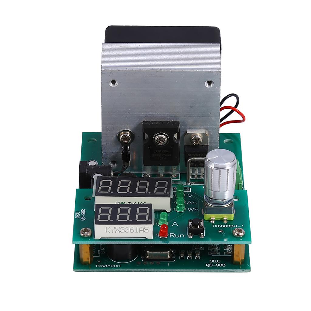
Setting Digital Illustration:
II: Electronic Load Mode:
1.
Turn on the power supply 12V boot into electronic load mode , ensuring
in a stopped state ( RUN does not light, otherwise the press of the
start stop switch to turn off the load ) connected to the power supply
under test to the test port input power (P+ P ) , pay attention not
to take the wrong polarity !
2. Set current and lower voltage
knob , turn the knob to set the value of the current setting position ,
then press the knob to change the setting digit, digital middle two
digits to the right of the indicator and digital indicator VA
simultaneously determine the current set position .
3. Press the
start stop switch, load began to run, RUN lights, power is applied
to the circuit under test is set to enter the discharge current, while
the upper display the actual input load voltage, when the voltage drops
below the set limit voltage RUN LED flashes and short beep alarm
buzzer accompanied.
4. The test procedure can be modified at any current, and if you need to modify the lower voltage to stop the load can modify.
Note: When
in alarm state, can only transfer a small current does not increase
!Tester automatic power down feature to save enough to save the set
parameters and run state, when the state again after power transmission
will complete before the power failure and restore data.
Battery Capacity Test Mode:
1. The test battery should be fully charged with a special charger.
2.
Give the tester is powered into the battery capacity test mode, connect
the battery current line to P+ P positive and negative terminals , if
you use four wire clamp test, while the four wire interface to the
positive and negative voltage test fixture is connected to V+ V port.
3.
Turn the knob to set the discharge current and discharge voltage (
referring to two specific methods : 2 ) , one press after
setting the start and stop switch , a battery tester and a first line
detection, automatic identification 2 4 line ( 2 wire line
identification presentation JS 2,4 identification JS 4, if an error
please stop the test and check the wiring ) , then enter the test , if
the fault code appears , refer to later explain .
The testing
process will round up digital noticeable battery voltage , current , and
the current discharge capacity Ah discharge energy Wh, when the
discharge end ( battery voltage is below the set voltage ) , the tester
displays the data stays in Ah and blink rapidly , with bee shortness
buzzer alarm.
5. Press the start and stop at the knob or switch
to stop the alarm , you can turn the knob to view the battery discharge
data , including discharge capacity Ah, Wh and discharge energy platform
voltage V, start stop button is pressed again , clear the data back to
the initial setting interface before testing the next section batteries.
Additional Information:
1.
Battery test process can adjust the discharge current , if you need to
re adjust the termination voltage , you can pause by pressing the
switch at the start and stop the discharge modification ( pause
discharge will return to the settings page , this time discharge data is
not lost , if necessary , you can long press clears the data until the
start stop switch 0.000Ah).
2. Tester automatic storage can
record setting parameters , and record all parameters and status at the
end of the test process and test power failure alarm status , re
transmission of all automatically restored.
Fault protection codes and meanings:
Err1: ultra high capacity test the battery voltage.
Err2: battery voltage is below the set termination voltage is not connected to the battery or the battery is reversed .
Err3: line resistance is too large or the battery can not afford to set the discharge current.
Err4: circuit failure .
Err6: working power is inappropriate , use a standard 12V power supply , and the supply current is not less than 0.5A.
otP: overheating protection.
Ert: temperature sensor failure or the temperature is too low.
ouP: ultra high voltage electron load mode.
oPP: under ultra high power electronic load mode instantly.
Package Includes:
1 x Multi function Module
Note
:
1, This product is a professional testing equipment , requiring the user have some basic electronic knowledge, or you
may be unable to use the device properly, possibly mishandled cause
unnecessary loss caused by the test device damage.
2, The default power adapter is not included.
3, Please allow 1 3mm error due to manual measurement. Thanks for your understanding.